Serial Lcd Display Pinout
NetMedia 2x16 Serial LCD Display Module V1.2 • RS232 compatible serial interface. Pinout Power and communications connections are made via header J5.
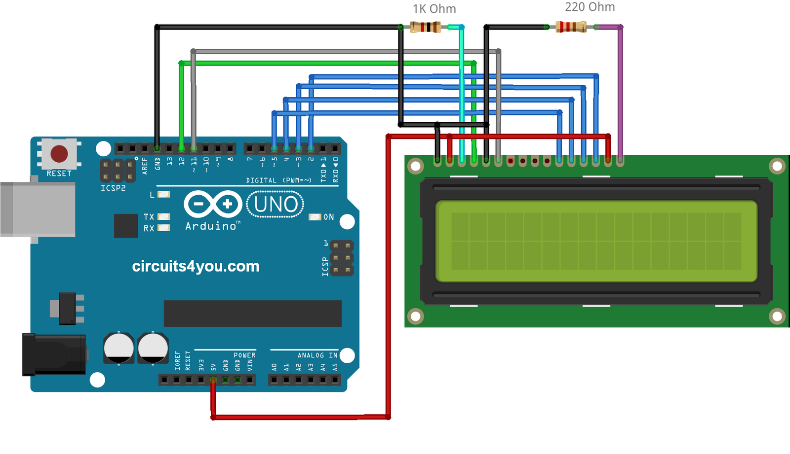
Next we'll connect up the backlight for the LCD. Connect pin 16 to ground and pin 15 to +5V. On the vast majority of LCDs (including ones from Adafruit) the LCD includes a series resistor for the LED backlight. If you happen to have one that does not include a resistor, you'll need to add one between 5V and pin 15. To calculate the value of the series resistor, look up the maximum backlight current and the typical backlight voltage drop from the data sheet. Subtract the voltage drop from 5 volts, then divide by the maximum current, then round up to the next standard resistor value. For example, if the backlight voltage drop is 3.5v typical and the rated current is 16mA, then the resistor should be (5 - 3.5)/0.016 = 93.75 ohms, or 100 ohms when rounded up to a standard value.
If you can't find the data sheet, then it should be safe to use a 220 ohm resistor, although a value this high may make the backlight rather dim. Bus WiringNow we'll finish up the wiring by connecting the data lines. There are 11 bus lines: D0 through D7 (8 data lines) and RS, EN, and RW. D0-D7 are the pins that have the raw data we send to the display. The RS pin lets the microcontroller tell the LCD whether it wants to display that data (as in, an ASCII character) or whether it is a command byte (like, change posistion of the cursor).
The EN pin is the 'enable' line we use this to tell the LCD when data is ready for reading. The RW pin is used to set the direction - whether we want to write to the display (common) or read from it (less common) The good news is that not all these pins are necessary for us to connect to the microcontroller (Arduino). RW for example, is not needed if we're only writing to the display (which is the most common thing to do anyways) so we can 'tie' it to ground. There is also a way to talk to the LCD using only 4 data pins instead of 8.


This saves us 4 pins! Why would you ever want to use 8 when you could use 4?
Arduino Lcd Pinout
We're not 100% sure but we think that in some cases its faster to use 8 - it takes twice as long to use 4 - and that speed is important. For us, the speed isn't so important so we'll save some pins! So to recap, we need 6 pins: RS, EN, D7, D6, D5, and D4 to talk to the LCD.
Arduino Lcd Serial Display
We'll be using the LiquidCrystal library to talk to the LCD so a lot of the annoying work of setting pins and such is taken care of. Another nice thing about this library is that you can use any Arduino pin to connect to the LCD pins. So after you go through this guide, you'll find it easy to swap around the pins if necessary. You have been successfully subscribed to the Notification List for this product and will therefore receive an e-mail from us when it is back in stock! For security reasons, an e-mail has been sent to you acknowledging your subscription. Please remember that this subscription will not result in you receiving any e-mail from us about anything other than the restocking of this item. If, for any reason, you would like to unsubscribe from the Notification List for this product you will find details of how to do so in the e-mail that has just been sent to you!